Designing the Case
Once I had the logical layout completed I switched to designing the case. The reason is that I wanted to make sure that when I performed the physical layout of the components they matched up perfectly with the case. To design the case I used Autodesk Fusion 360.
I started off by creating a sketch of the physical layout of the keys:
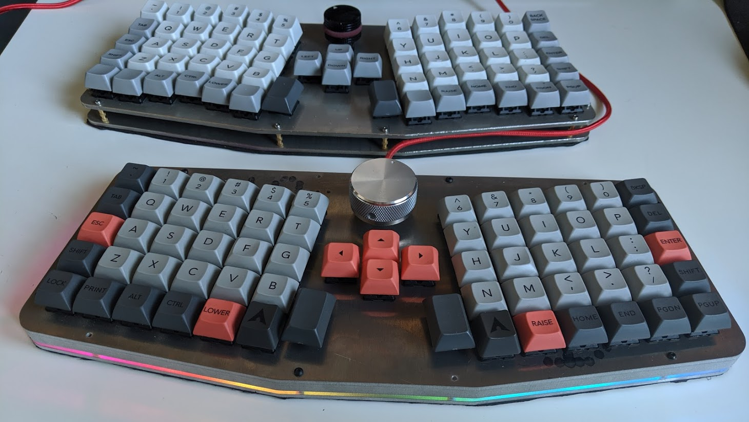
The sketch includes a lot of extra lines and this is because at the time I wanted the option to have non-staggered keys. Here is a picture of v1 and v3 for an example of the differences. As you can see the top keyboard (v1) has staggered keys, where the bottom keyboard (v3) does not.
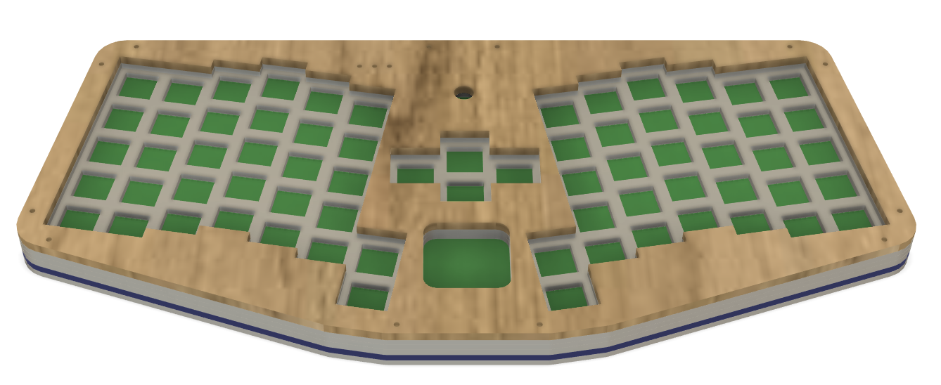
Once the sketch was completed I then extruded the different layers to create the completed case. This process was quite complicated due to the thickness of the materials. I had to go back and forth between the material thicknesses available at BigBlueSaw and the space needed between the different layers to come up with the most compact version. During this process I eventually decided to switch the USB from the bottom of the PCB to the top. This allowed me to make the keyboard much thinner.
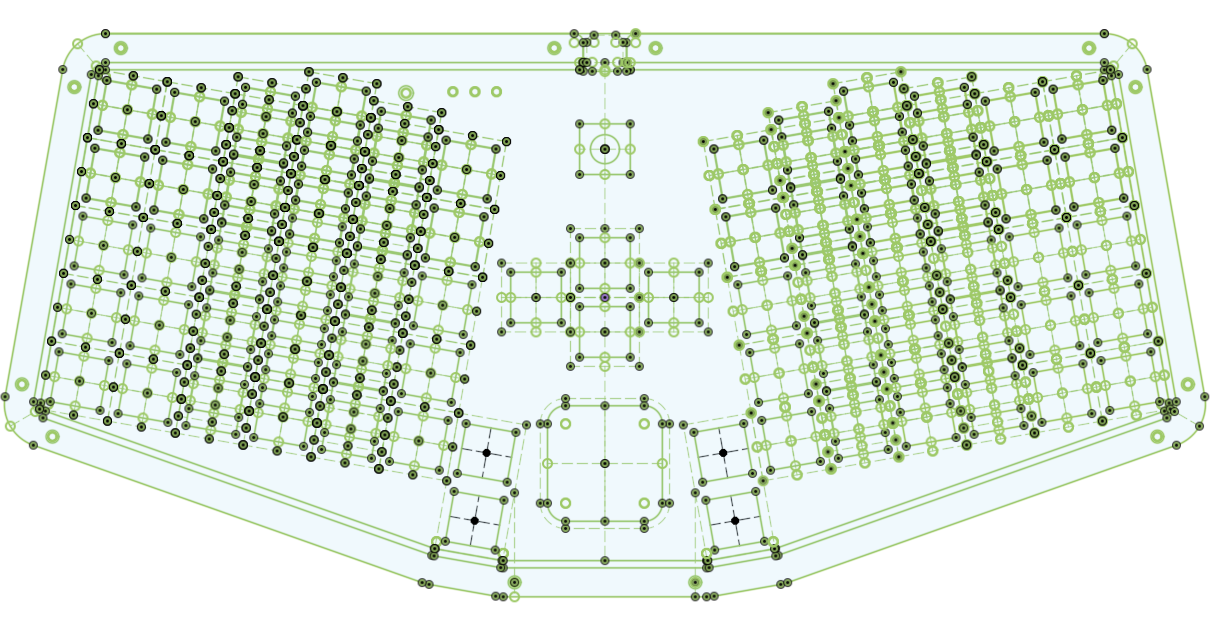
Now that I had the case ready to go I was able to export a 2D drawing from Fusion 360 and import it into KiCAD. This provided an outline of the case, keys, reset switch, etc… that I could reference to make sure everything fit exactly.