Putting it all Together
Once I had the PCBs in hand along with all of the components needed I was able to solder the components.
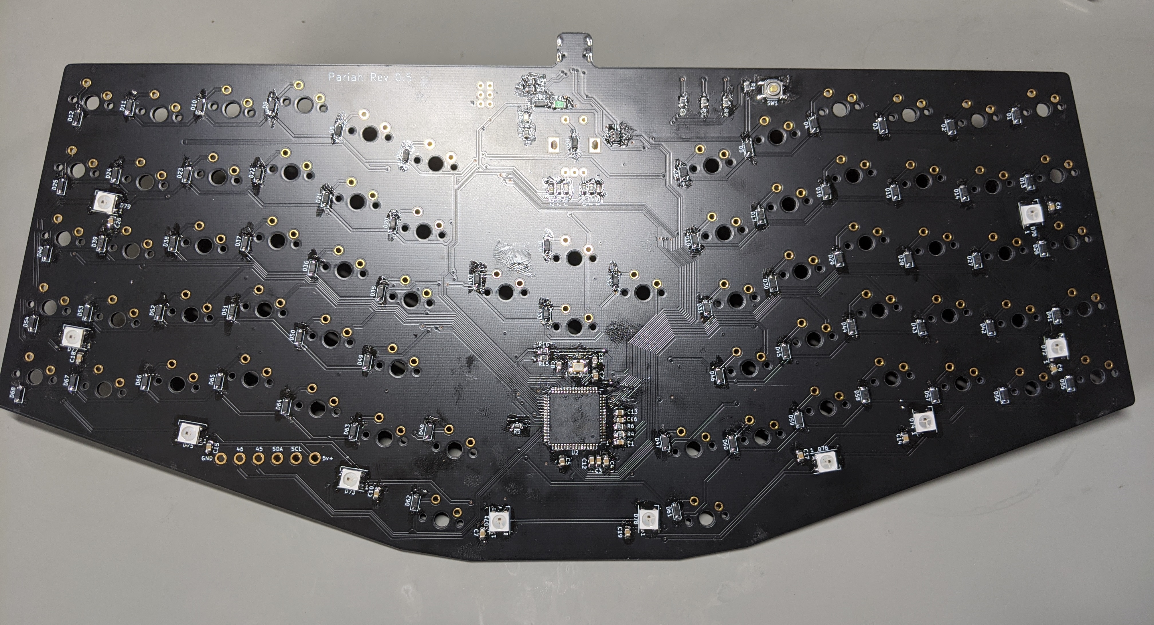
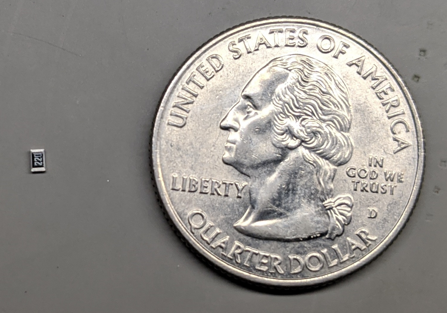
This is pretty tedious as the parts are pretty small. For example, all Resistors and Capacitors are size 0805. Here is a picture of a resistor to give you an idea of what that looks like.
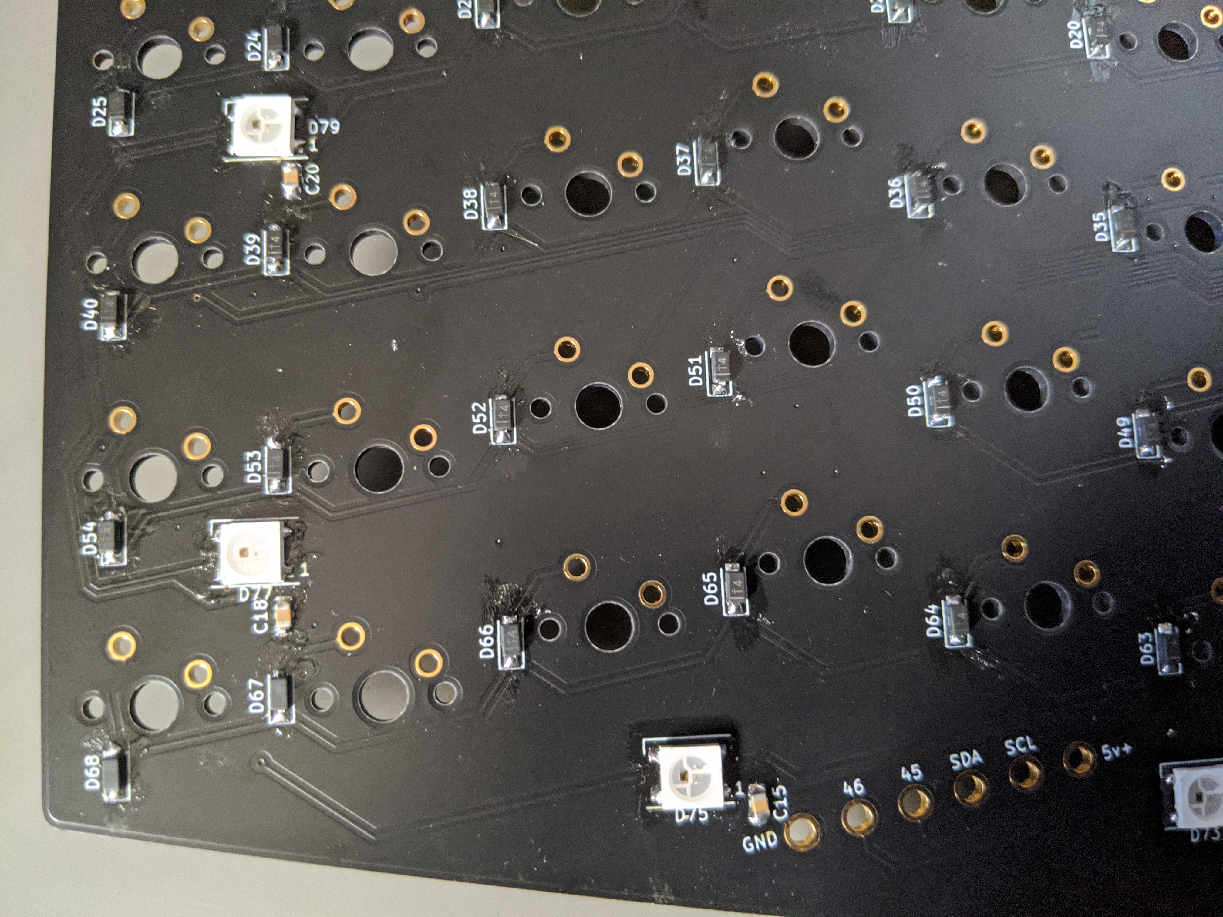
Here is a close-up of one side of the bottom of the PCB
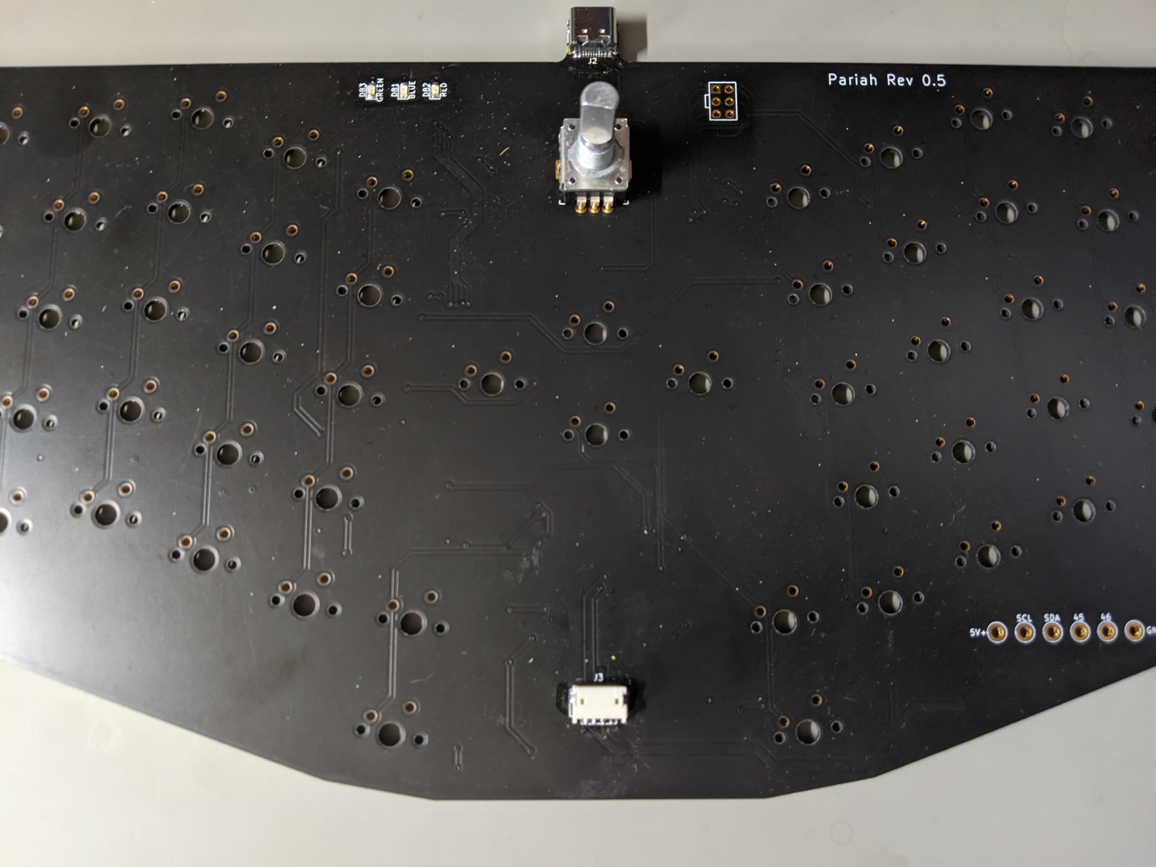
There are only a couple of components that need to be soldered to the top of the board: the indicator LEDs, the Rotary Encoder, the OLED connector and the USB connector.
At this point I can test out the board by loading up the firmware and manually making connections between the switch connections.